During the transit of airplanes, the conditions of the infrastructures are crucial. Aeronautical pavements can consist of large concrete slabs that rise and fall depending on the temperature and weather conditions. Perhaps only a few millimeters, but the continuous passage of airplanes causes a progressive degradation of the pavement.
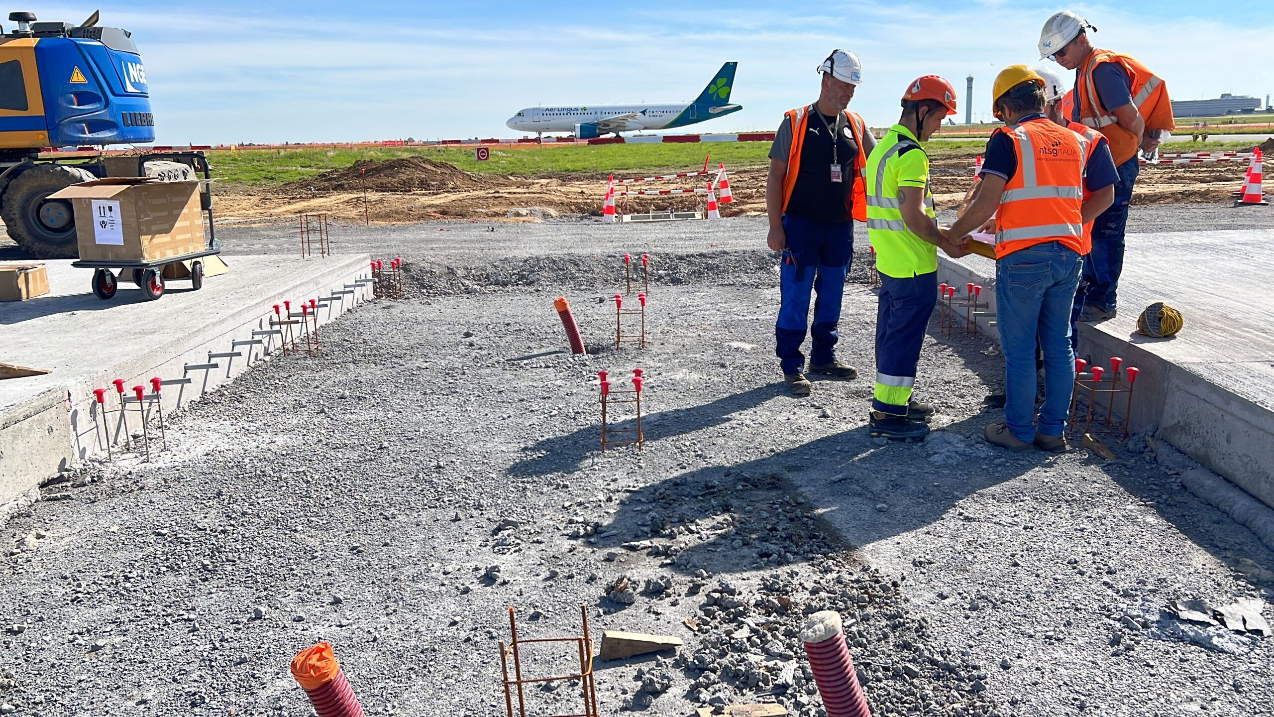
Charles De Gaulle Airport in Paris, the second busiest in Europe, has therefore initiated an experimental study to analyze the stresses that occur on airport pavement. They have asked NTSG Italy (Mon.it Group) to create a monitoring project for the slabs to understand the variations that the structure undergoes over time and consequently understand its health.
The goal is to accurately plan maintenance activities based on the actual conditions of the runway and improve the understanding of the stresses suffered by the slabs to refine the theoretical models used for pavement design
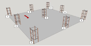
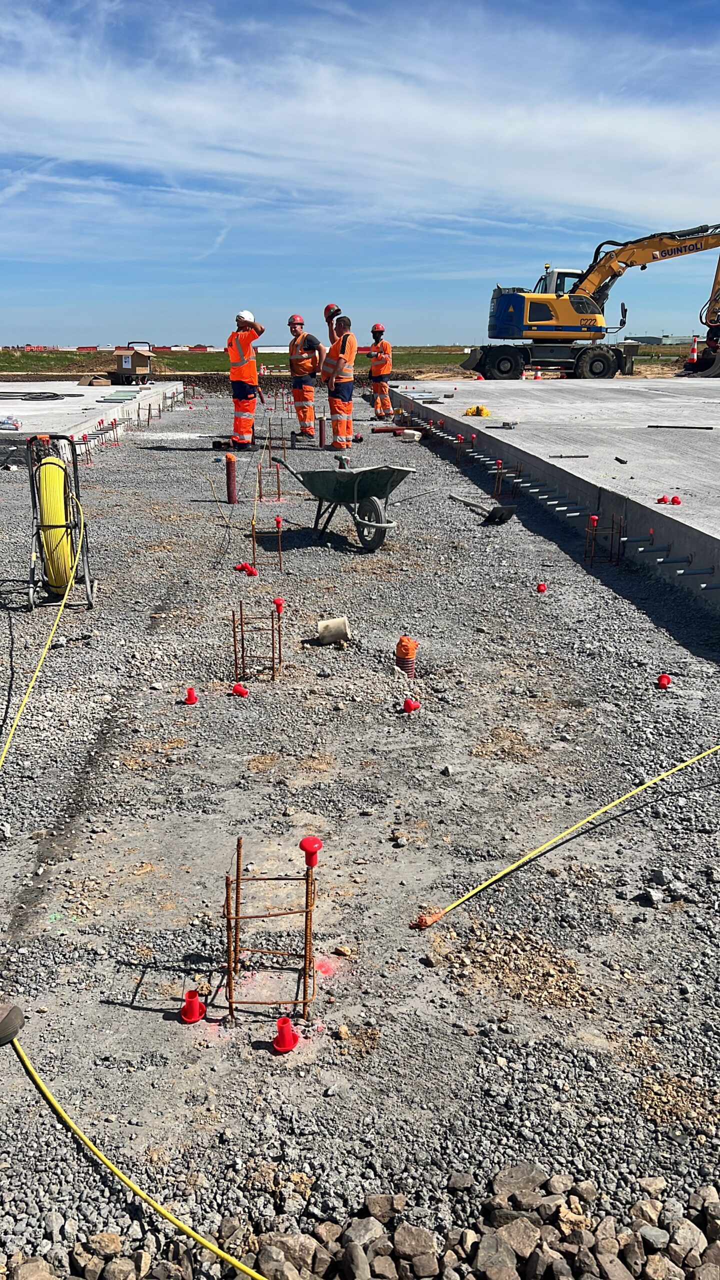
Some of the airport pavements are made up of different layers of material. The top layer consists of Slabs: 5×5 m cement blocks with a thickness of about 60 cm.
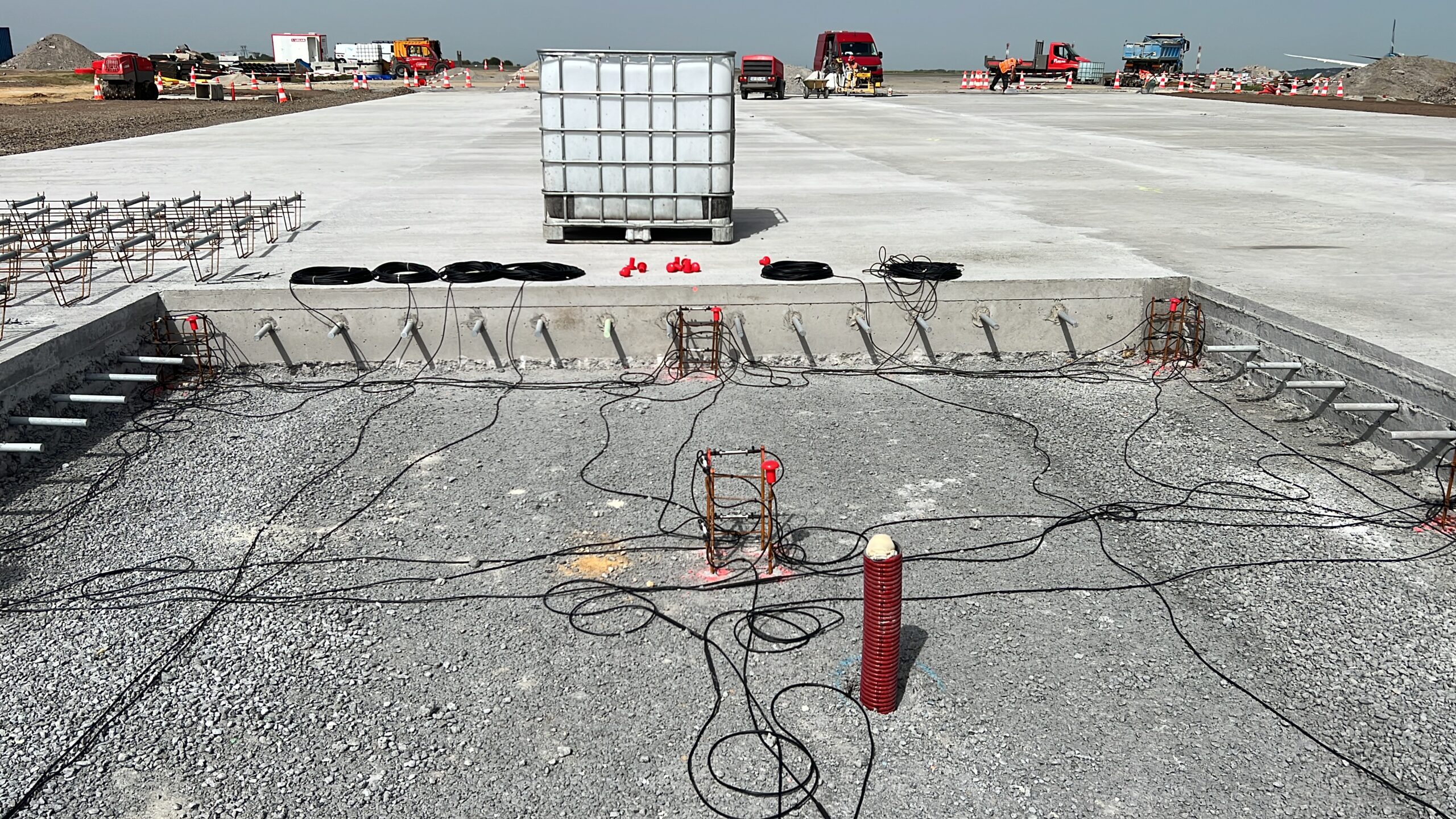
The project involves the installation of fiber optic sensors inside the Slabs on a section of airport pavement, during the pavement construction phase.
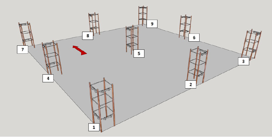
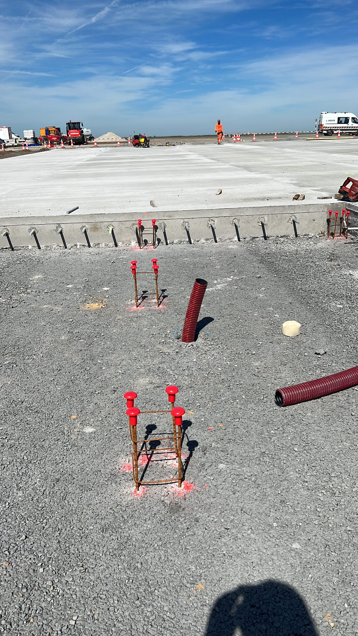
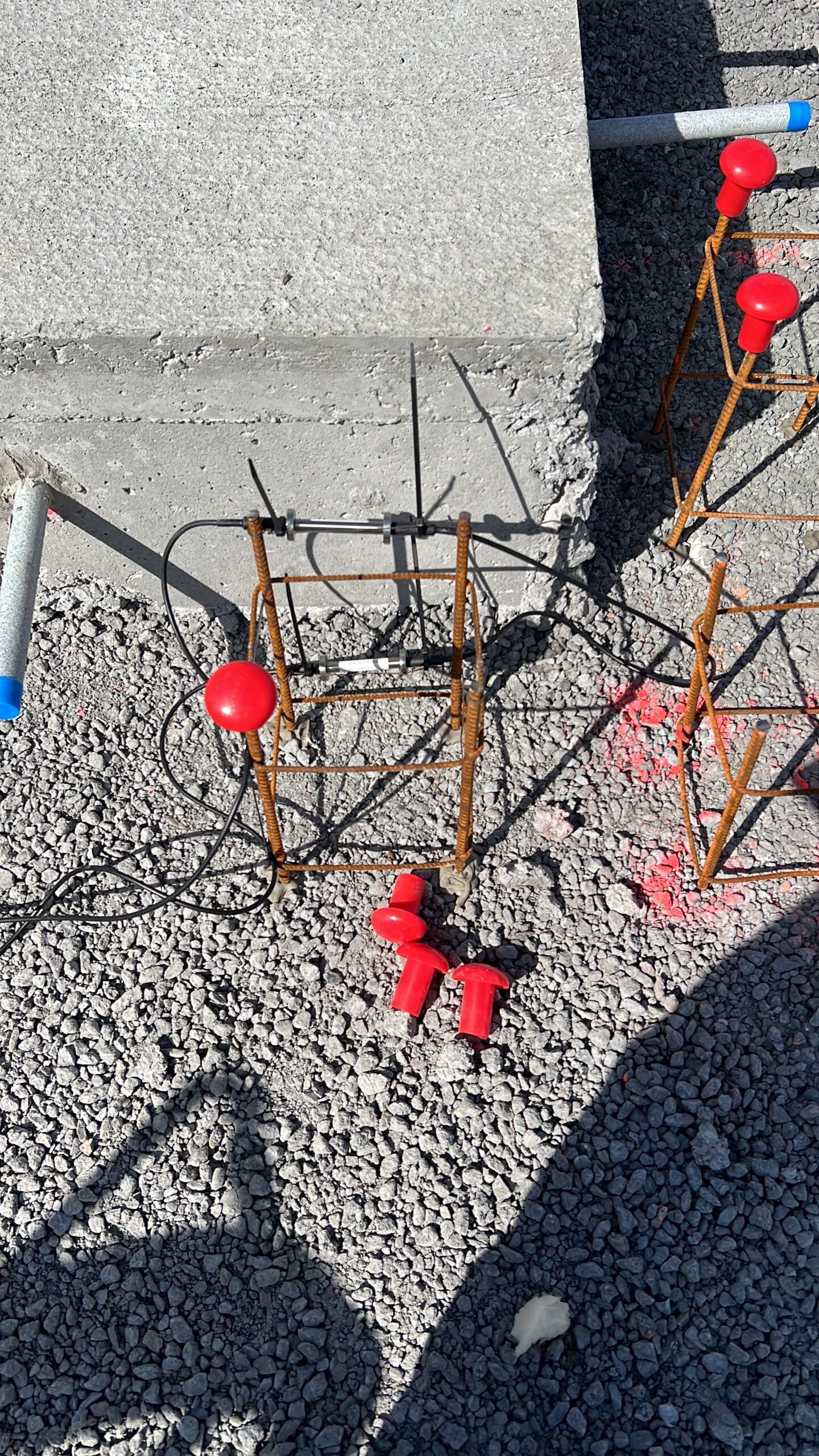
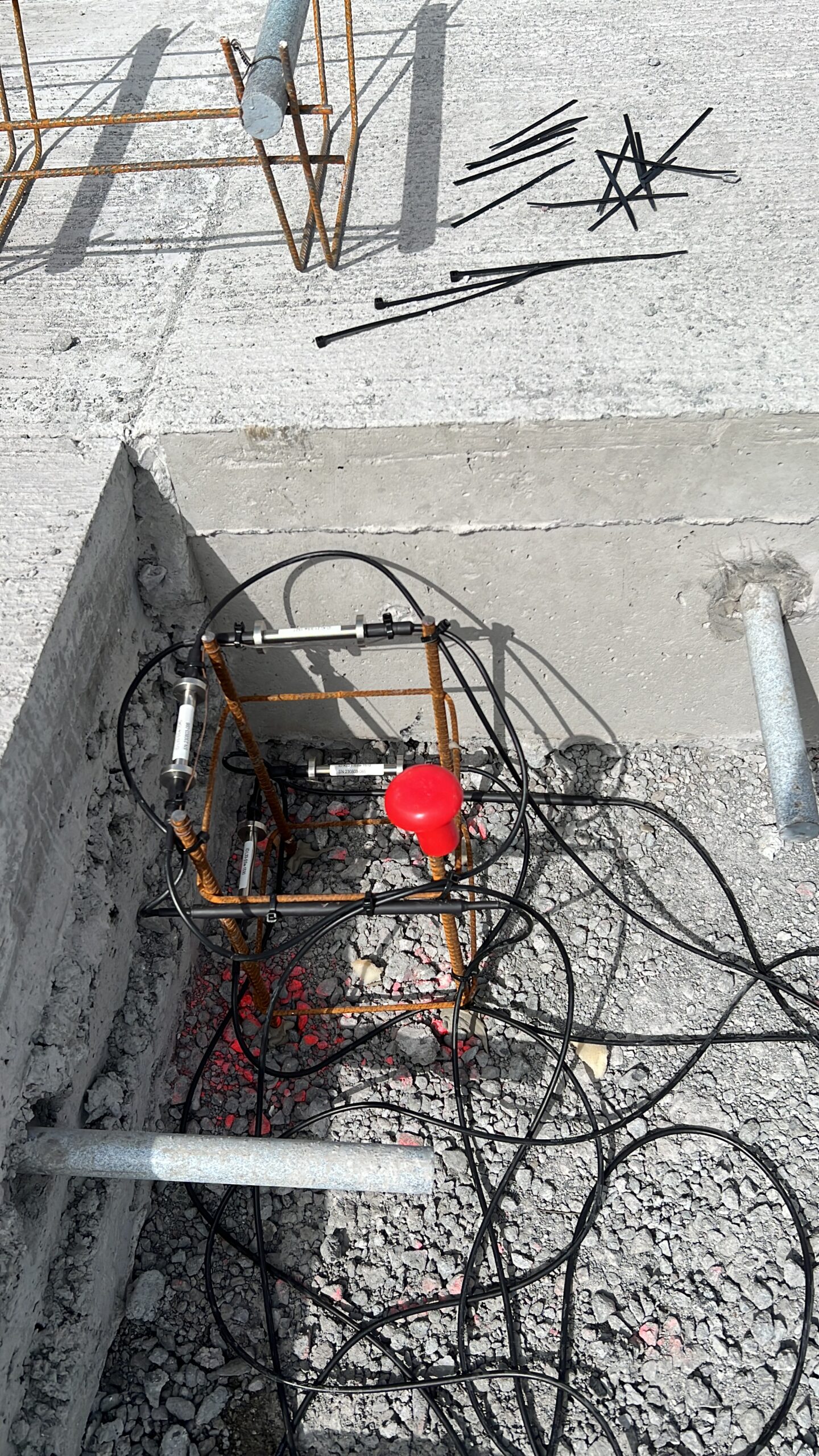
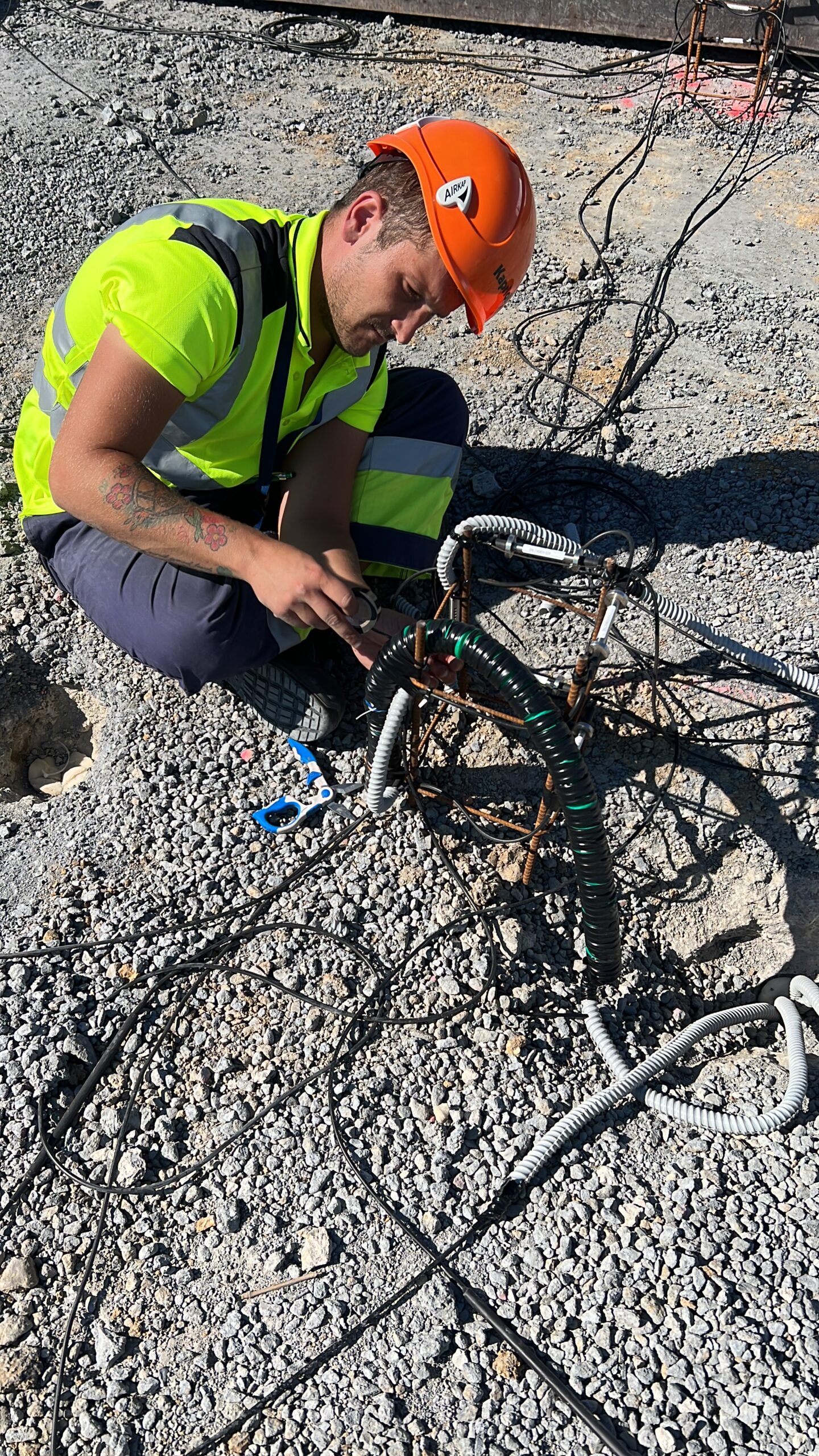
In these Slabs, there are iron towers where we have installed MS (strain) and MST (strain and temperature) sensors, humidity sensors, and thermal sensors.
Once the sensors are installed on the towers, the cement casting that constitutes the Slab is carried out, creating a single block: in this way, we can monitor the deformations of the cement due to thermal phenomena and vehicle passage.
In the center of some Slabs, a humidity sensor has been installed to monitor the percentage inside the cement. Furthermore, triplets of thermal sensors are provided on the thickness of the Slabs to measure the thermal gradient and verify the temperature variation within them.
Nello strato di asfalto drenante sottostante le Dalle, sono stati installati dei PIEZOMETRI per verificare l’eventuale presenza di infiltrazioni di acqua.
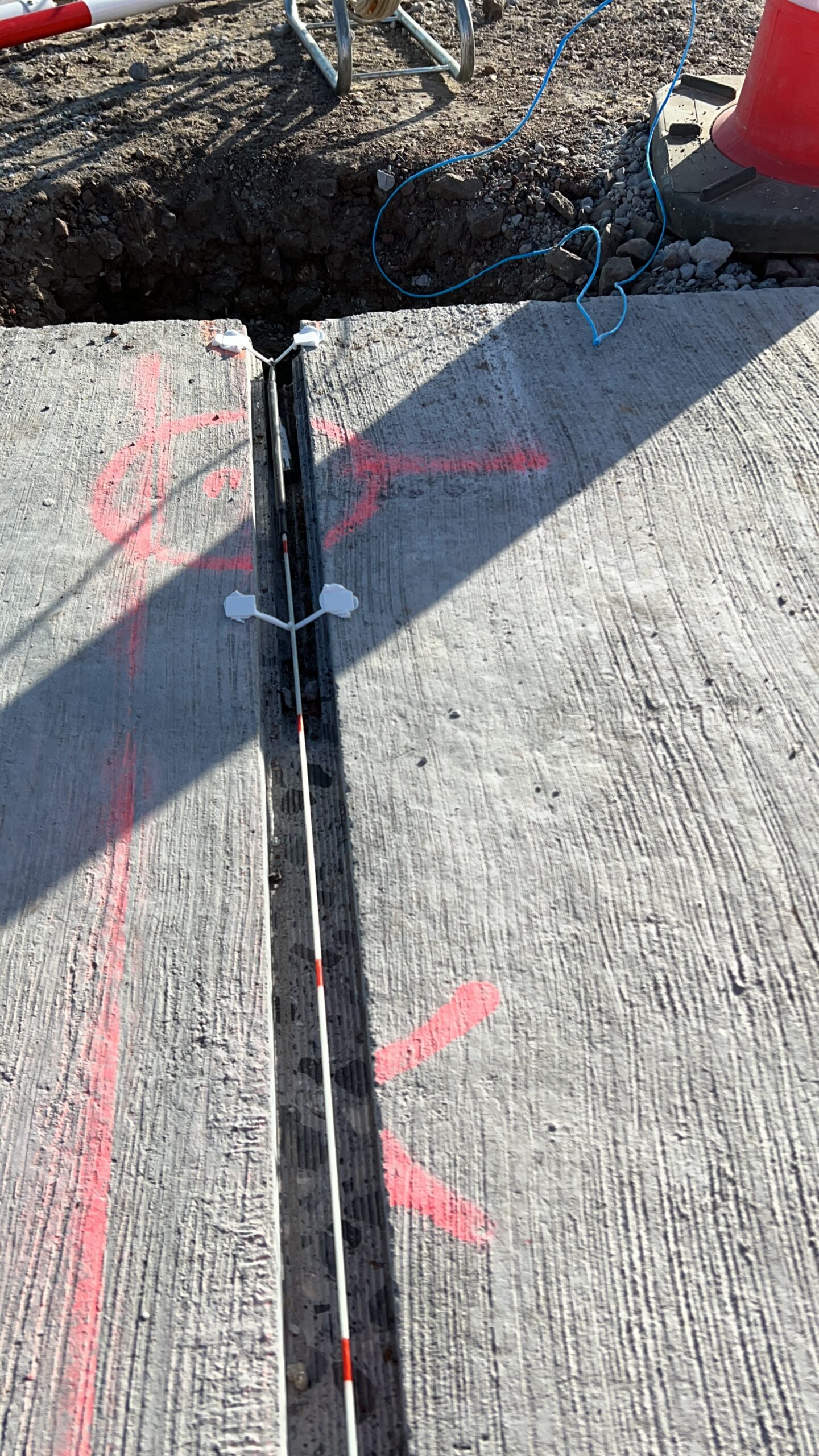
Another area of experimentation is the analysis of the relative movement of Adjacent Slabs induced by external stresses (aircraft/vehicle transit).
For this purpose, the joints between adjacent Slabs have been sensorized.”
PHASE 2 – Recognition of transit vehicles
Experimental Application
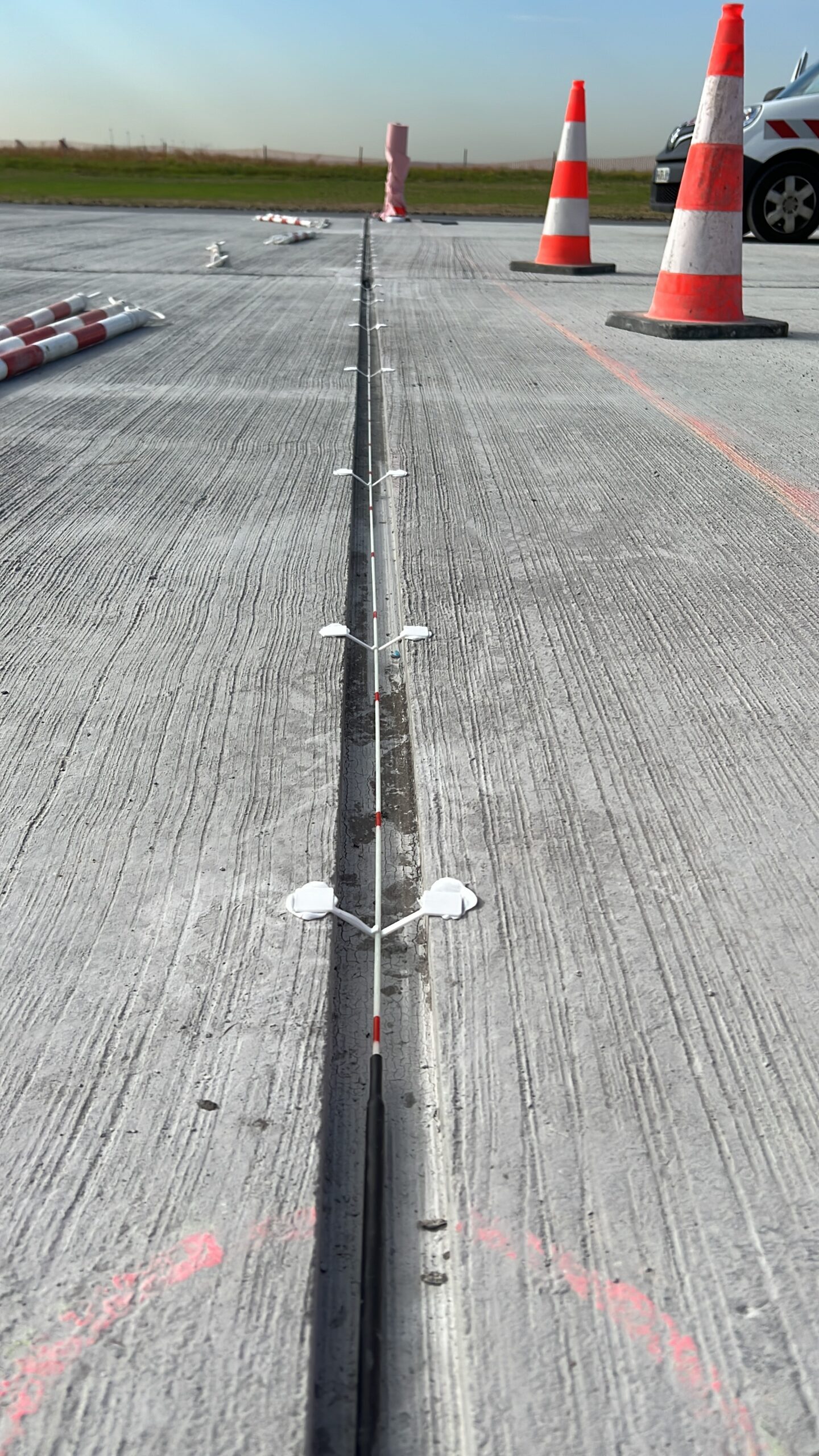
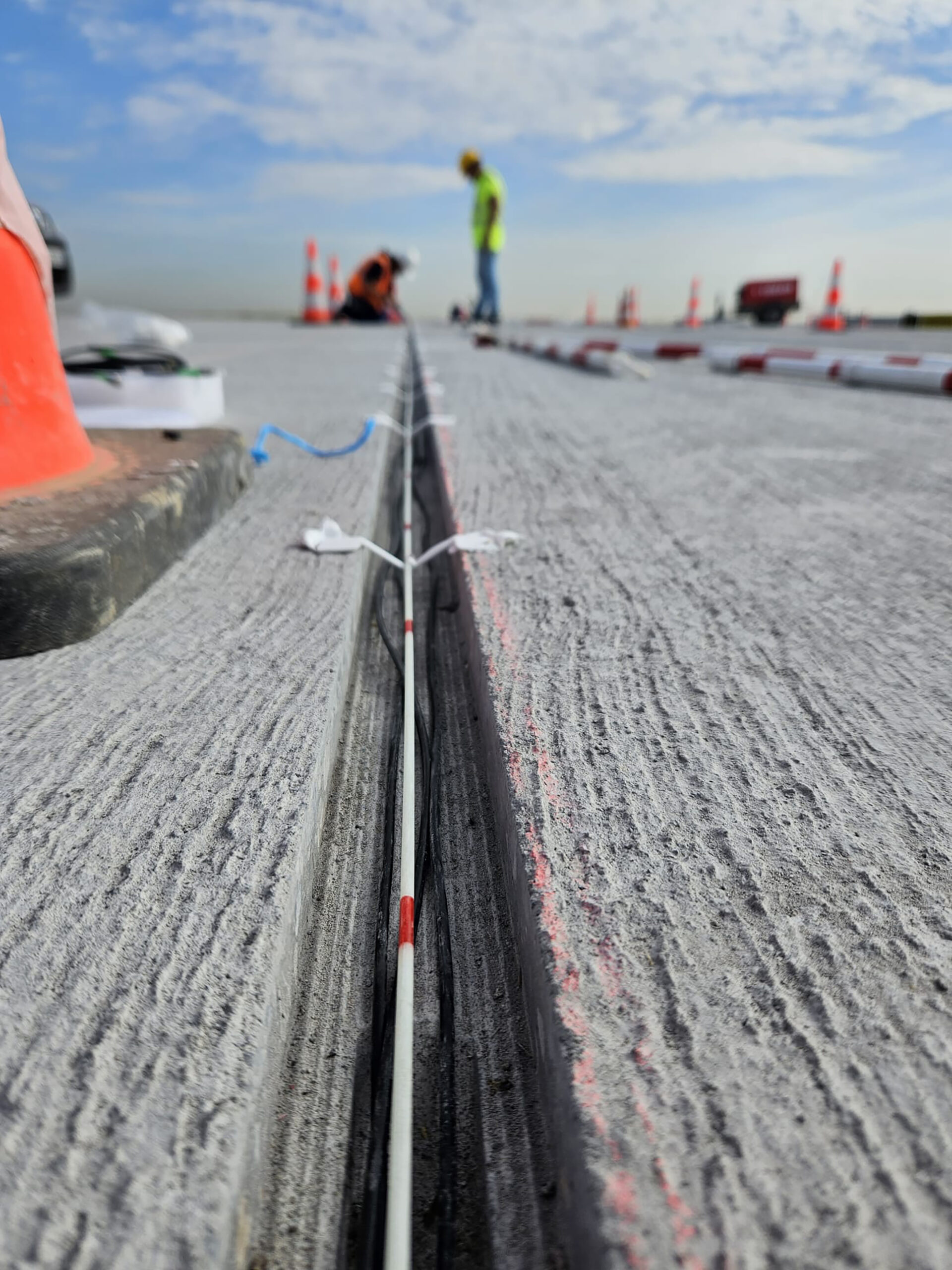
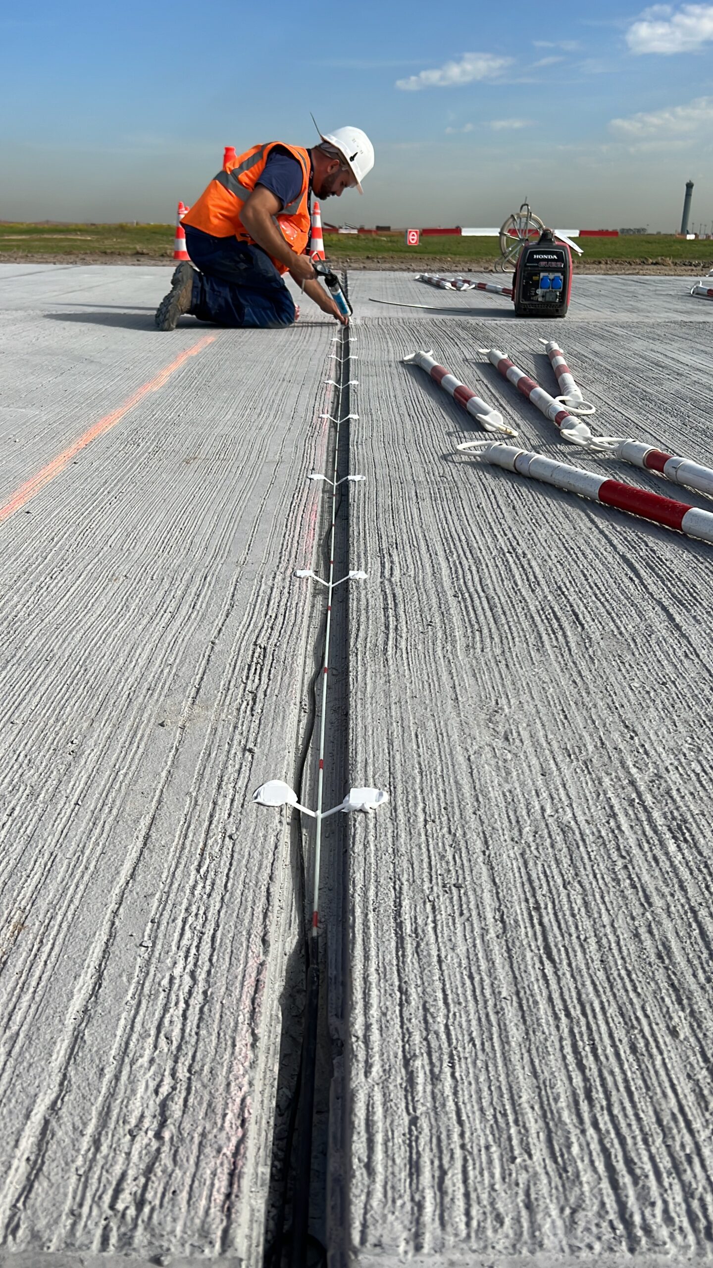
In this case, out target is to trace a portion of the trajectory of the aircraft in transit to characterize their lateral movement on the infrastructure.
To install the sensors, a trench is excavated in the concrete, 2.5 cm wide and 5 cm deep, where the optical fibers are positioned, supported by interlocking supports to maintain all the fibers at the same height
On the same runway, GFRP (strain) sensors and 4 temperature sensors will be installed at the edges.
The installed sensors are as follows: